User interface, part 2
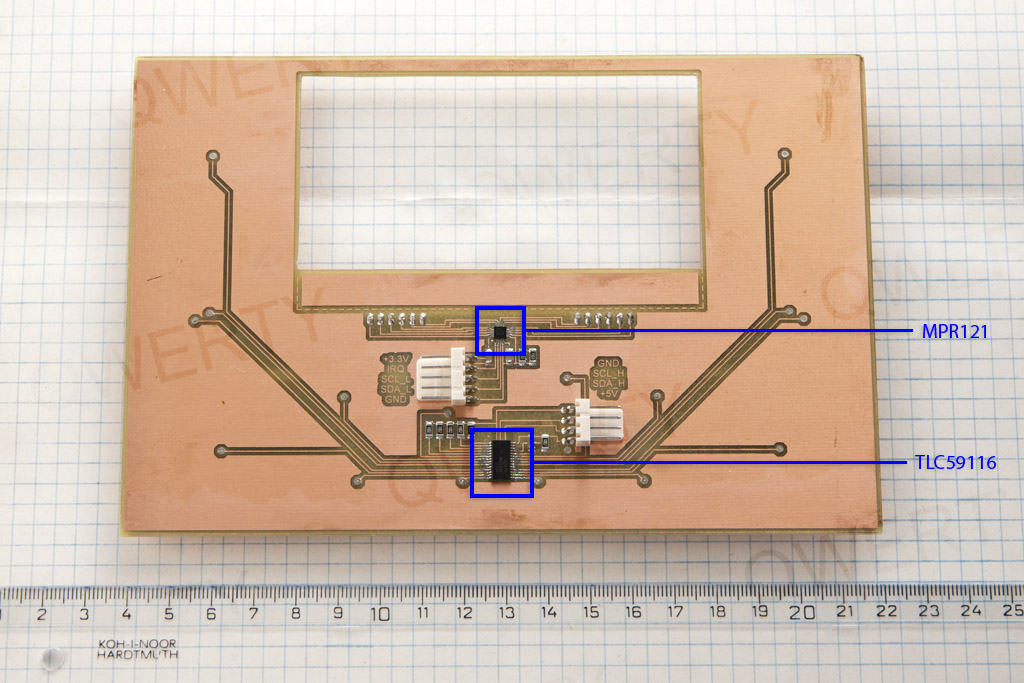
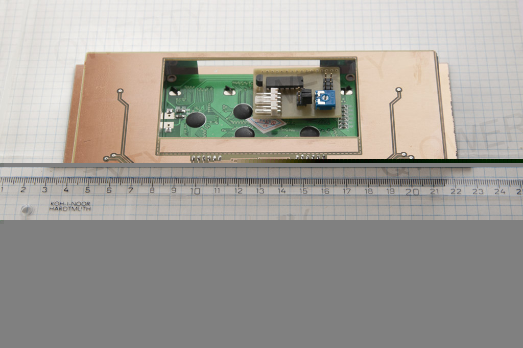
Board size is 18 x 12 cm, double sided, exact fit on acrylic glass component.
- MPR121 – capacitive touch sensor controller for I2C bus, 12 touch electrodes supported (datasheet).
It is 3 mm x 3 mm 20 lead QFN package IC – if you are able to etch 0.2 mm tracks, I bet will handle to solder it. This works for me: no stencil, manual spread of solder paste via thin needle to IC itself, not the PCB; hot air gun reflow; solder wick to clean up traces. Trick is to apply as little solder paste to IC pins as you are able to apply to avoid bridges under the chip. I use 0.8 mm needle – a bit harder to get the solder paste through it but not impossible. Applying solder paste to PCB did not work for me. When applying it to IC directly you have better control and possibility to remove excessive paste using a knife or similar tool – apply the paste close to IC edges.
- TLC59116 – 16-channel LED driver for I2C bus (datasheet). Very easy to solder (compared to IC above).
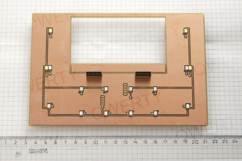
12 pcs blue LED, 4 pcs white LED, 120 deg. viewing angle.
Pin headers to stack the other board.
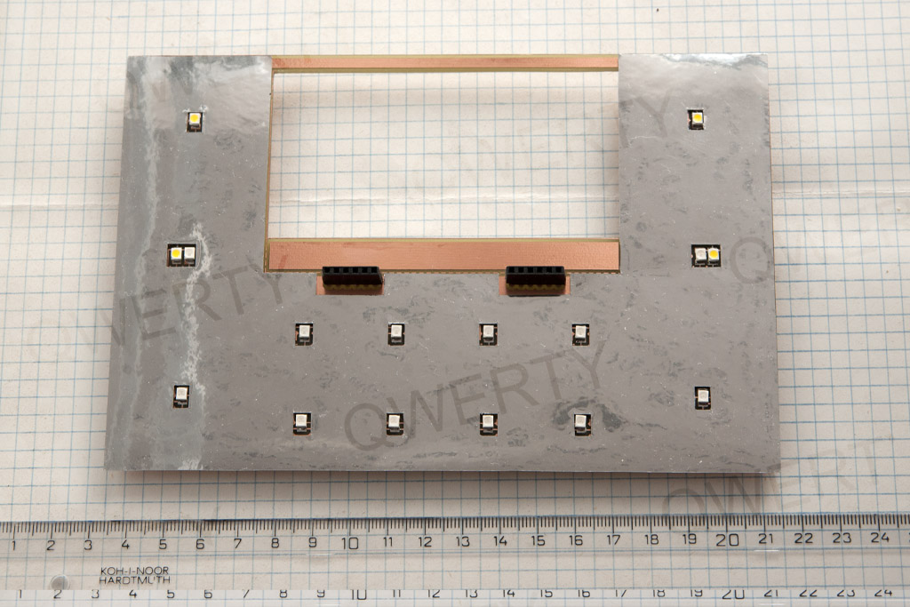
Applied reflex layer from the previous post. No need to stick it to PCB.
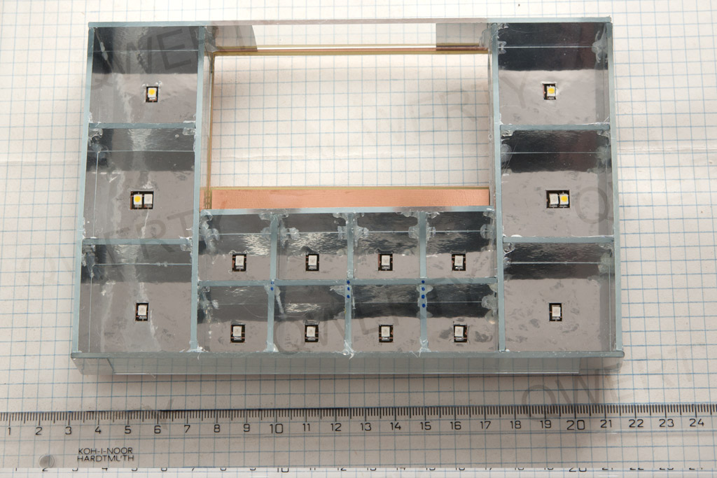
With the acrylic glass component in place.
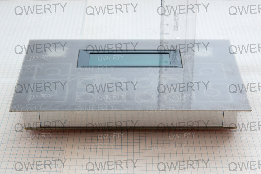
All layers stacked. I do not stick layers together. 2x 6-pin headers seem to be strong enough to hold it all together on the assumption there is no gap between layers. Shorten pins to remove existing gap if necessary. Very easy to disassemble this way.
Page 1 – Introduction
Page 2 – Controller board
Page 3 – User interface
Page 4 – User interface, part 2
Page 5 – The case
Page 6 – Frame building
Page 7 – Case modification
Page 8 – Shelf installation
Page 9 – Hello World! video
Page 10 – Observations and conclusion
Recent Comments