User interface
I did not mention I decided for a capacitance touch sensing instead of using push buttons for several reasons like limited design etc.
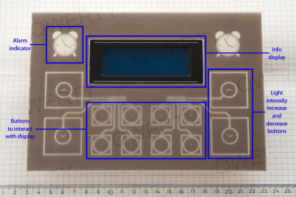
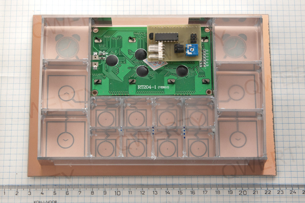
- Board size is 20 x 14 cm, single sided. It is mainly based on info display PCB dimensions plus extra area to take rather large buttons for light control.
- Info display – HD44780 controller based LCD, 20 x 4 characters, blue backlight, white characters.
- Buttons to interact with display – with functions related to info shown on LCD, basically 4 pairs of general purpose increase/decrease buttons.
- Light intensity increase and decrease buttons – primary function is to control two independent lights; used to turn off/snooze the alarm as well.
- Alarm indicator – alarm on/off indicator, active alarm/snooze indicator.

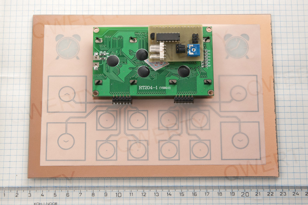
- I2C/GPIO adapter – based on PCF8574 IC, common wiring found on internet, with a pot to adjust contrast; to reduce wiring.
- Touch electrodes – there are several application notes on electrode size, shape, spacing, grounding areas, track widths and lengths etc. It is a must-read to get basic knowledge but after all you end up with a common sense design. I did a mistake in my previous “capacitance touch” project and placed some components too close to electrodes and their tracks. I was getting many false touch indications; hard to troubleshoot.
- You may notice pins below the info display – for stacking another board.
Other thing I did not mention is the button backlighting. This fulfills the “good visible interface” requirement. It would be much more complicated to backlight common push buttons unless you decide to pay for something like illuminated MEC switches; no guarantee you will find what you need. Anyway, this is a DIY project, I stick to this concept as much as possible.
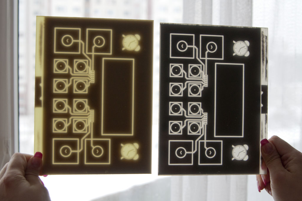
One important thing. When you backlight a PCB and you care about the color on the other side, search for PCB with neutral base laminate (dielectricum). I have one last board on my shelf that has almost colourless laminate, no color cast. If I use blue LED, PCB just dims intensity a bit but I still get blue color. Imagine you use blue LED with a greenish PCB laminate. Guess what color you get. Anyway, does anybody know where to buy PCB with grey or clear laminate? See this picture to see the difference. AFAIK, FR4 material is colourless itself but there are additives needed for automated optical inspection process – this is what I was told. Local vendor I bought that clear PCB from is out of stock with them. Other solution would be to use a thin PCB instead of 1.5 or 1.6 mm that would not impact color of traversing light that much but it would be too flex to be a touch panel I bet.
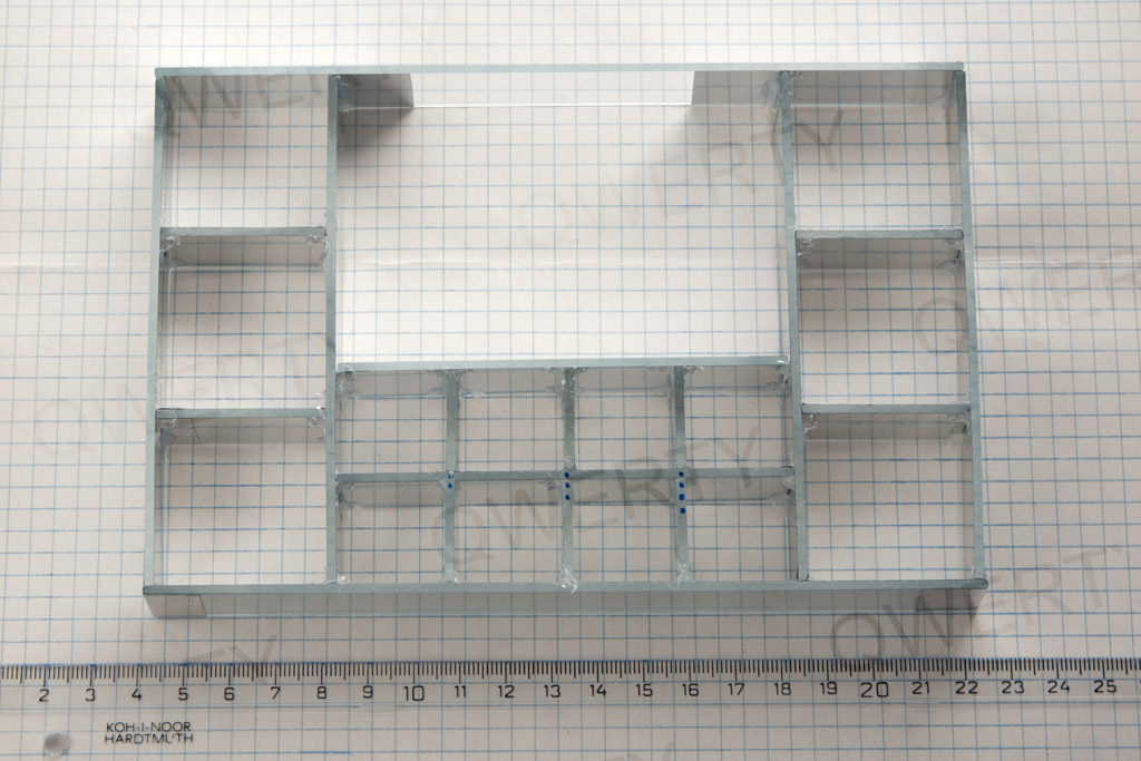
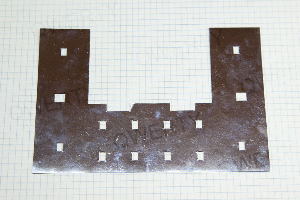
I want each element on panel to have individual backlight. It is necessary to build cells for all of them. I use acrylic glass, 2 mm thick. I cut the sheet to many 2 cm wide strips afterward cutted to required length. Using a hot glue gun to assemble the whole thing works fine and is very quick.
To prevent light crosstalk between cells, spray the whole thing with black color.
LEDs have given viewing angle. Based on area you need to backlight, used LEDs may not be able to cover all the area and you get very uneven backlight. You can make the cells higher if your size limitations allow it. If there is a depth limit, you can apply some reflex layer to each cell. I bought A4-size chrome self-adhesive foil on eBay and sticked it on cut acrylic strips before joining them (no black spray needed). My internal opinion: such reflex layer provides better light distribution.
A piece of tracing paper as a light diffuser to soften light. PCB has a internal structure, softened light makes it a bit blured.
Let’s stack prepared layers.
I will use another reflex layer to maximize amount of light reaching the PCB. Made from the same reflex foil I sticked to acrylic glass strips. Placed on the top, reflex side facing the touch electrodes of course. You can start without that reflex stuff to see the backlight quality. I just like details.
Page 1 – Introduction
Page 2 – Controller board
Page 3 – User interface
Page 4 – User interface, part 2
Page 5 – The case
Page 6 – Frame building
Page 7 – Case modification
Page 8 – Shelf installation
Page 9 – Hello World! video
Page 10 – Observations and conclusion
Recent Comments