Riadiaca doska
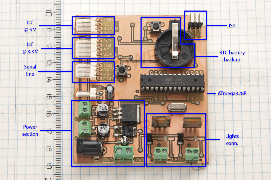
- The power section takes 12 V as input which is needed for lights. Reduced to 5 V and 3.3 V for other components, available via screw terminals as well for future use.
- Serial line and ISP – I found comfortable to use UNO board with removed 328, wired to my boards for serial communication when debugging instead of having USB/serial adapter. ISP, no comment.
- I2C lines – pulled up to 5 V and 3.3 V for used ICs, common logic level converter with MOSFETs used.
- Lights outputs – screw terminals to connect LED lights. Switched by MOSFETs driven by PWM output from 328.
- ATmega328P – running at 16 MHz, standard standalone wiring, reset button. Left unpopulated soldering pads next to IC holder for future use.
- Battery – power backup for RTC IC, with IC reset button.
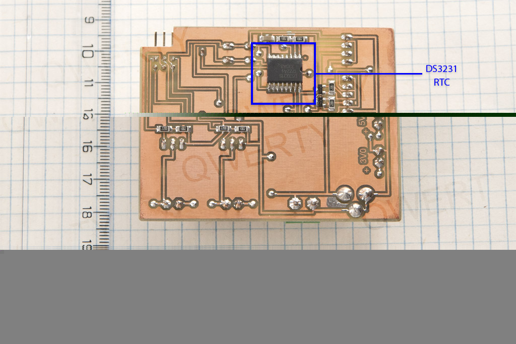
- DS3231 – real time clock IC. I preferred this one to DS1307 for this project because of the precision.
- 555 – operating in astable multivibrator mode to drive a piezo buzzer. I preferred this to use tone() & delay() combo.
As you can see I use home made PCB, as I always do. You can see I placed some SMD components at bottom layer. Reason is obvious – to minimize via count. I leave as much copper on board as possible/reasonable to save etching solution. I usually use UV curable solder mask from eBay as well but I just ran out of it. No silkscreen.
Page 1 – Introduction
Page 2 – Controller board
Page 3 – User interface
Page 4 – User interface, part 2
Page 5 – The case
Page 6 – Frame building
Page 7 – Case modification
Page 8 – Shelf installation
Page 9 – Hello World! video
Page 10 – Observations and conclusion
Recent Comments